Categories
- Tech & News (21)
- Pipes & Fittings (12)
- Valves & Pumps (54)
- Equipment & Tools (6)
- Facilities & Chemicals (10)
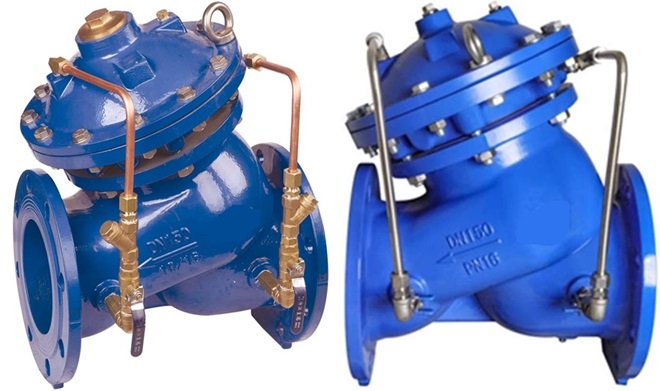
Pump (slow shut) control valves, ductile iron, double flanged with hydraulic manifold: copper tubing (left) and stainless steel tubing (right).
At Metalsin, we supply ductile iron pump control valves (also known as “slow-shut control valve”) to waterworks applications. The pump control valve is a diaphragm‑type, hydraulically driven valve mounted at the pump outlet. It taps the pipeline’s own pressure as its power source to coordinate perfectly with the centrifugal pump’s characteristic curve. On start‑up, it delays opening gently—allowing pressure to build and avoiding a sudden surge—then, during normal operation, it stays fully open as long as its inlet pressure exceeds outlet pressure. When the pump stops or the valve’s outlet pressure rises above its inlet pressure, the valve snaps shut quickly to block backflow, then closes softly to dissipate any remaining energy. This controlled opening and closing sequence eliminates water hammer, protects the pump from reverse flow, and ensures a smooth, reliable water supply.
The pump control valve primarily comprises several key components: the valve body, bonnet, seat, main disc, slow-closing disc, diaphragm, stem, and regulating valves. The lower chamber under the diaphragm is connected via external conduit tubing to the valve inlet, while the upper chamber is connected to the valve outlet. Before the pump starts working, outlet pressure is present in the valve’s outlet. This pressure is transmitted through the conduit tubing into the upper chamber, forcing the diaphragm and stem downward so that the slow‑closing disc & main disc are pressed firmly against the seat, keeping the valve fully closed.
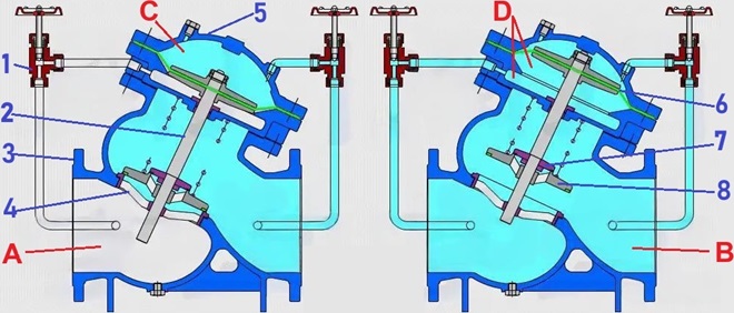
Illustration of the pump control valve’s working principles: 1 – regulating valve; 2 – stem; 3 – body; 4 – seat; 5 – bonnet; 6 – diaphragm; 7 – slow-closing disc; 8 – main disc. A – valve inlet; B – valve outlet; C – upper chamber; D – lower chamber.
At pump start‑up, as valve-inlet pressure builds, it travels via the conduit tubing into the lower chamber under the diaphragm. Once this inlet pressure surpasses the outlet pressure of the valve, the diaphragm lifts, carrying the stem and slow-closing disc upward to unseat the main disc. Under the force of the inlet fluid, the main disc then opens, and the fluid from the upper chamber returns to the outlet through the conduit tubing. When the pump stops, the valve’s inlet pressure drops. At zero flow, the main valve disc rapidly snaps shut under the influence of gravity and the return spring. The small bypass (re-flow) holes on the main disc allow outlet fluid to flow back to the inlet, extending the valve’s closing duration and reducing water‑hammer effects. Finally, as outlet pressure rebuilds and is conveyed through the conduit tubing to the upper chamber, the diaphragm and slow-closing disc descend slowly, closing the bypass port and fully sealing the valve. The fluid in the lower chamber then drains back to the inlet via the conduit tubing.
The pump control valves are generally designed in accordance with CJ/T 167 and JB/T 10674. The flanged ends shall be cast integrally with the valve body in accordance with ASME B16.1 Class 125 (for ANSI/AWWA compliance) or EN 1092-1 or 1092-2 (for EN, BS, and DIN compliance). Working pressure: PN 10, PN 16; 200 psi, 250 psi, 300 psi. Working temperature: 0°C~80°C. Both exterior and interior surfaces shall be epoxy powder coated (RAL 5005 or 5015). Click to view the drawing, dimensions, flow characteristics & material specification for the pump control valve.
By adjusting the regulating valves on the inlet and outlet conduits, the user can precisely control the valve‘s slow‑opening and slow‑closing intervals: smaller openings lengthen these times, while larger ones shorten them, with adjustment range from 3 to 120 seconds. The pump control valve’s opening‑and‑closing differential pressure is kept at or below 0.05 MPa, and after shutdown, any water‑hammer pressure is limited to 1.3–1.5 times the pump’s rated outlet pressure. The pump may reverse at up to 1.2 times its rated speed for no more than two minutes. To maintain proper slow‑closing performance, do not install a foot valve at the pump inlet; if a foot valve is necessary, choose a slow‑closing type. Finally, a built-in strainer is required to prevent debris from clogging the regulating valves and tubing and ensure reliable valve operation.