Categories
- Tech & News (10)
- Pipes & Fittings (12)
- Valves & Pumps (40)
- Equipment & Tools (6)
- Facilities & Chemicals (10)
The remote float valve is a diaphragm-type hydraulic valve that uses the pressure within its own pipeline as its driving force. Equipped with an adjustable horizontal float ball, it regulates water injection to maintain a steady water level—even when flow rates vary. This reliable design makes it ideal for applications such as reservoirs and water tanks where precise liquid level control is essential.

Remote float valves supplied by Metalsin for waterworks, double flanged, ANSI/AWWA or BS EN compliant.
At Metalsin, we supply remote float control valves for waterworks meeting a series of international standards. These remote float valves have the following design features:
The remote float control valve operates through a coordinated system involving an angle valve, a float ball, and a float rod. It also includes a needle valve, a small strainer, and a ball valve. Under normal conditions, water enters the main valve’s upper control chamber (No. 2) via the needle valve (No. 1) from the inlet. When the tank’s water level falls below the preset threshold, the angle valve (No. 4) opens, allowing water from the upper chamber to discharge into the tank. This discharge lowers the pressure in the chamber, which causes the main valve to open and inject water into the tank.

Overview of the remote float valves’ operating principles.
Conversely, as the water level rises, the float ball (No. 6) gradually forces the angle valve to close. This action increases the pressure in the upper chamber, prompting the diaphragm to slowly close the valve disc. When the water level reaches the desired setting, the angle valve fully closes, and the main valve shuts off the water supply. Additionally, the needle valve regulates the closing speed to prevent water hammer, while the ball valve (No. 3) can be manually closed for emergency shut-off if the float ball loses control.
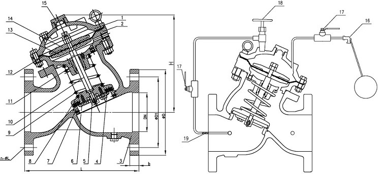
Typical drawing of the remote float valves, Y type, double flanged.
| Part No. | Part Name | Material Spec. |
|---|---|---|
| 1 | Upper Bonnet | ASTM A536 65-45-12 EN-GJS-450-10 |
| 2 | Middle Bonnet | ASTM A536 65-45-12 EN-GJS-450-10 |
| 3 | Valve Body | ASTM A536 65-45-12 EN-GJS-450-10 |
| 4 | Main Gasket | EPDM |
| 5 | Disc Head | SS 304 |
| 6 | Main Gland | ASTM A536 65-45-12 EN-GJS-450-10 |
| 7 | Seat | SS 304 |
| 8 | Main Disc | ASTM A536 65-45-12 EN-GJS-450-10 |
| 9 | Spring | SS 304 |
| 10 | Stem | SS 304 |
| 11 | Bushing | Brass |
| 12 | Diaphragm | EPDM |
| 13 | Bottom Gland | ASTM A536 65-45-12 EN-GJS-450-10 |
| 14 | Upper Gland | ASTM A536 65-45-12 EN-GJS-450-10 |
| 15 | Cap Plug | SS 304, Brass |
| 16 | Pilot Valve | SS 304, Brass |
| 17 | Ball Valve | SS 304, Brass |
| 18 | Needle Valve | SS 304, Brass |
| 19 | Built-in Strainer | SS 304, Brass |
Design standards: AWWA C530; CJ/T 219, JB/T 10674. End flange dimensions shall be furnished in accordance with EN 1092-2 PN 10 & PN 16 or ASME B16.1 Class 125. Working pressures: PN 10, PN 16; 175 psi, 200 psi, 250 psi, 300 psi. Working temperatures: 0°C~80°C. Both interior & exterior surfaces should be FBE coated as per AWWA C550 in RAL 5005 or 5015 color. Sizes: 2″~16″ for ANSI/AWWA systems; DN50~DN600 for BS/EN systems. Click to view the dimensions & flow characteristics of remote float valves for ANSI/AWWA and BS/EN water systems, respectively.