Categories
- Tech & News (17)
- Pipes & Fittings (12)
- Valves & Pumps (52)
- Equipment & Tools (6)
- Facilities & Chemicals (10)
A post indicator is a modified variant of extended stem device used primarily in fire protection systems to provide a visual indication of whether a buried or otherwise inaccessible valve (typically a non-rising stem gate valve) is in the open or closed position. It also serves as a means to operate the valve remotely from above ground, often featuring a telescopic extended stem that can be set to the desired length during installation. This helps ensure that the valve can be quickly accessed and controlled in emergency situations such as fires. The post indicator device shall be designed and manufactured in accordance with UL 789 and FM 1110, available in sizes 4″ (DN100) through 24″ (DN600). It is typically UL listed and FM approved. Post indicators are primarily used to control the water supply gate valves for the sprinkler, flood, foam, and riser systems connected to the building’s private fire protection network.
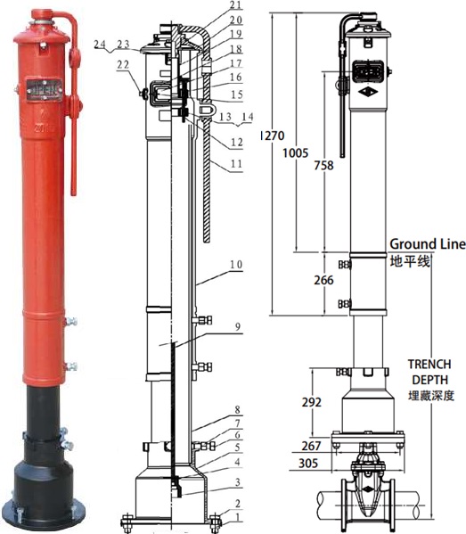
The photo and drawing of a post indicator for NRS gate valves in the fire protection system.
Typically, the non-rising stem gate valve with an attached post indicator features a resilient seating and a mounting flange at the top. As shown in the drawing, both the gate valve and lower part of the post indicator are installed underground in a trench. The gate valve may be furnished with flanged ends, mechanical joint ends, or grooved ends. They shall be designed in accordance with a series of international standards such as BS 5163, EN 1171, AWWA C515, and DIN 3352, etc. Both interior and exterior surfaces of the upper post indicator shall be FBE coated in RAL 3000 color, while those of the lower part shall be coated in black color.
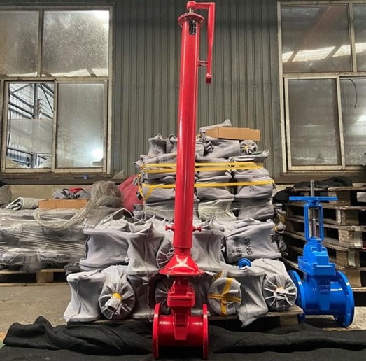
A post indicator with a BS 5163 NRS gate valve, to Bahrain.
The post indicator operates using a dual-function L-type wrench, which engages an operating nut to drive the valve stem. This mechanism converts rotational motion into a lifting movement via the thread, clearly indicating whether the valve is open or closed. In addition, the indicator features a “U”-shaped padlock anti-theft device that locks the gate valve after operation, preventing unauthorized adjustments or disassembly. Its design also allows for easy installation, as the trench depth can be adjusted as needed for a quick on-site setup. Click to view more details about the maintenance, installation and operation of the post indicator for NRS gate valves used in fire-protection underground systems.
| Part No. | Part Name | Material Spec. |
|---|---|---|
| 1 | Hex Nut | C.S. + Zinc SS 304, SS 316 |
| 2 | Hex Bolt | C.S. + Zinc SS 304, SS 316 |
| 3 | Socket | EN-GJS-450-10 A536 65-45-10 |
| 4 | Pin | SS 304 |
| 5 | Flange | EN-GJS-450-10 A536 65-45-10 |
| 6 | Hex Bolt | C.S. + Zinc SS 304, SS 316 |
| 7 | Hex Nut | C.S. + Zinc SS 304, SS 316 |
| 8 | Sleeve | ASTM A53 Gr.B |
| 9 | Stem | SS 420, SS 431 |
| 10 | Body | EN-GJS-450-10 A536 65-45-10 |
| 11 | L Wrench | EN-GJS-450-10 A536 65-45-10 |
| 12 | Carrier Nut | SS 304, Brass |
| 13 | Hex Bolt | C.S. + Zinc SS 304, SS 316 |
| 14 | Hex Nut | C.S. + Zinc SS 304, SS 316 |
| 15 | Hex Bolt | C.S. + Zinc SS 304, SS 316 |
| 16 | Instruction Plate | EN-GJS-450-10 A536 65-45-10 |
| 17 | Sight Glass | Plexiglass |
| 18 | Gasket | PTFE |
| 19 | Op. Nut | SS 304 |
| 20 | Top Cover | EN-GJS-450-10 A536 65-45-10 |
| 21 | Snap Ring | SS 304 |
| 22 | Plug | M.I. + HDG |
| 23 | Square Nut | C.S. + Zinc SS 304, SS 316 |
| 24 | Hex Bolt | C.S. + Zinc SS 304, SS 316 |
| Sizes | Trench Depth | |
| 4" | Min. | 1070 |
| Max. | 1080 | |
| 5" | Min. | 1120 |
| Max. | 1920 | |
| 6" | Min. | 1160 |
| Max. | 1960 | |
| 8" | Min. | 1250 |
| Max. | 2050 | |
| 10" | Min. | 1330 |
| Max. | 2130 | |
| 12" | Min. | 1430 |
| Max. | 2230 | |
| 14" | Min. | 1640 |
| Max. | 2440 | |
| 16" | Min. | 1620 |
| Max. | 2420 | |
| 18" | Min. | 1570 |
| Max. | 2570 | |
| 20" | Min. | 1790 |
| Max. | 2590 | |
| 24" | Min. | 1950 |
| Max. | 2750 | |