Categories
- Tech & News (21)
- Pipes & Fittings (12)
- Valves & Pumps (54)
- Equipment & Tools (6)
- Facilities & Chemicals (10)
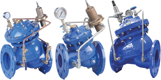
Various pressure relief & sustaining valves supplied for waterworks by Metalsin Tech.
The pressure relief and sustaining valve is a diaphragm-type hydraulic control valve that is actuated by the hydraulic pressure within its own pipeline. Its key advantage is its dual functionality—it can serve as either a pressure relief valve or a pressure sustaining valve. When operating as a pressure relief valve, it automatically releases any upstream pressure that exceeds a preset limit, thereby protecting the pipeline and associated equipment from damage caused by high or sudden pressure surges. Conversely, when used as a pressure sustaining valve, it maintains the upstream water supply pressure at a predetermined value to ensure that the upstream area receives prioritized water supply.
The pressure relief & sustaining valve supplied by Metalsin is a diaphragm-type, pilot-operated hydraulic control valve. It is equipped with an adjustable pilot valve, needle valve, compact strainer, ball valve, and other components.

The illustration of working principles of pressure relief & sustaining valves (PRSV) in water systems.
The pressure relief & sustaining valve supplied by Metalsin features a spherical, Y-shaped body with a full-diameter design that delivers strong flow capacity, low head loss, and an optimized flow channel to minimize turbulence and cavitation hazards. Its integrated, easy-to-assemble diaphragm functions as a soft piston for smooth, sensitive, and precise control, while the dual-chamber main valve protects the diaphragm from high-pressure impacts and debris, ensuring a service life of over one million cycles. Additionally, the external connecting pipe is equipped with a self-cleaning strainer to reduce maintenance, and the valve operates automatically without external power, saving energy and enabling unmanned operation. A throttling hole linking the lower chamber to the back outlet further guarantees gentle response, stable pressure, and reduced pipeline vibration and noise.
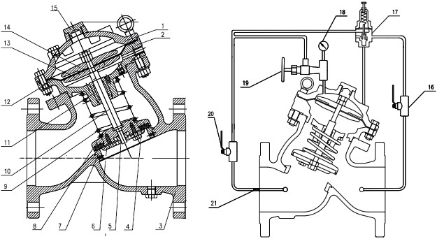
Typical drawing of pressure relief & sustaining valves for water systems.
| Part No. | Part Name | Material Spec. |
|---|---|---|
| 1 | Upper Bonnet | EN-GJS-450-10 ASTM A536 65-45-12 |
| 2 | Middle Bonnet | EN-GJS-450-10 ASTM A536 65-45-12 |
| 3 | Valve Body | EN-GJS-450-10 ASTM A536 65-45-12 |
| 4 | Gasket | EPDM |
| 5 | Main Disc Cap | SS 304 |
| 6 | Main Disc Gland | EN-GJS-450-10 ASTM A536 65-45-12 |
| 7 | Seat | SS 304 |
| 8 | Main Disc | EN-GJS-450-10 ASTM A536 65-45-12 |
| 9 | Spring | SS 304 |
| 10 | Stem | SS 304 |
| 11 | Bushing | Brass |
| 12 | Diaphragm | EPDM |
| 13 | Bottom Gland | EN-GJS-450-10 ASTM A536 65-45-12 |
| 14 | Upper Gland | EN-GJS-450-10 ASTM A536 65-45-12 |
| 15 | Bonnet Plug | SS 304, Brass |
| 16 | Ball Valve | Brass Hpb59-1 |
| 17 | Pilot Valve | SS 304, Brass |
| 18 | Pressure Gauge | SS 304 |
| 19 | Needle Valve | SS 304, Brass |
| 20 | Ball Valve | Brass Hpb59-1 |
| 21 | Built-in Strainer | SS 304 |
Design standards: AWWA C530, CJ/T 219,JB/T 10674,BS EN 558 serial 10. Flanged connection shall be made to ASME B16.1 Class 125 or EN 1092-2. Working pressures: PN 10, PN 16; 175 psi, 200 psi, 250 psi, 300 psi. Working temperature: 0~80°C in waterworks systems. Both interior and exterior surfaces should be epoxy coated in RAL 5005 or 5015 color as per AWWA C550. Click to view the dimensions and flow characteristics for pressure relief & sustaining valves designed to ASME/AWWA waterworks systems and EN BS/DIN waterworks systems.